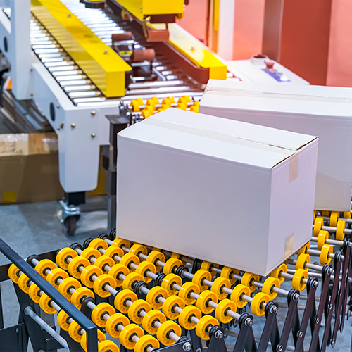


Efficient conveyor systems are crucial for factories and warehouses to ensure smooth movement of goods both within the facility and during loading and unloading. Today, a wide variety of conveyors is available, each with specific advantages. Among these, flexible powered roller conveyor systems stand out for their convenience and versatility, making them a popular choice in modern logistics and material handling. These motorized flexible conveyor systems are designed to adapt their shape to changing layout requirements. Let’s explore the operational capabilities of these flexible conveyors and understand their unique design.
Defining the Workhorse: What Are Flexible Powered Roller Conveyors?
At its core, a flexible powered roller conveyor is defined by two fundamental characteristics: shape-adjustability and electric motorization.
Shape-Adjustability: Unlike fixed-frame conveyors, FPRs are constructed from interlocking segments or a continuous flexible bed that allows them to bend laterally, curve, and often extend and retract in length. This enables them to snake around obstacles, bridge gaps between dock and truck, and be reconfigured as facility layouts evolve.
Electric Motorization: Each roller, or groups of rollers, is driven by an integrated electric motor (typically a low-voltage DC motor within the roller itself, known as a Motorized Drive Roller or MDR). This provides the positive driving force needed to move heavy loads up inclines, control speed, and implement accumulation strategies without the complexity of external drive shafts or line shafts.

This powerful synergy makes the FPR the unit of choice for:
Truck and Container Loading/Unloading: Their ability to extend and retract makes them perfect for reaching deep into a trailer, drastically reducing manual labor and improving dock-to-stock times.
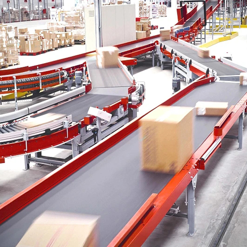
Dynamic Warehouse Operations: They can be easily deployed for temporary sortation, cross-docking, or to create pop-up distribution lines during peak seasons.
Adaptable Assembly Lines: In manufacturing environments where product lines change frequently, FPRs can be quickly reconfigured to support new workflows.
Distribution and Fulfillment Centers: They excel at moving goods between packing stations, sorters, and shipping, adapting to daily fluctuations in volume and product flow.
Blueprint for Success: Key Design Considerations
Designing an FPR is an exercise in balancing competing priorities. The following considerations form the critical foundation upon which all design decisions are made.
1. Weight Bearing Capacity and Structural Dynamics
The primary mandate of any conveyor is to bear load. For FPRs, this analysis is threefold:
Individual Item Weight: The maximum weight of a single item dictates the required robustness of each roller, its axle, and the surrounding frame. Engineers must calculate the deflection (bending) of the roller under maximum load to ensure smooth, uninterrupted operation without risk of failure.
Overall System Load: The cumulative weight of multiple items on the conveyor simultaneously must be supported by the entire structure. This influences the choice of frame material (typically high-tensile aluminum or steel), the thickness of the frame profiles, and the spacing of support legs.
Load Distribution: Is the load uniform, or are there points of concentrated weight? Palletized goods may have weight focused on the edges, requiring reinforced side channels, while irregularly shaped items might necessitate closer roller pitch (the distance between rollers) to ensure at least three rollers are supporting the load at all times.
2. Power Architecture and Distribution
The "powered" aspect of the FPR is its most technically complex element. The design must ensure consistent, reliable, and efficient power delivery across a system that is meant to move and change shape.
Motor Selection: The choice between AC and DC motors is fundamental. Traditional AC motors are powerful and robust for constant-speed applications but are less efficient for stop-start operations. Modern MDRs almost exclusively use 24V or 48V DC motors integrated into the roller. These offer superior control, high starting torque, and are inherently compatible with zone-based accumulation logic. Their low-voltage operation also enhances safety.
Zoned Power Distribution: Power is not delivered uniformly. The conveyor is divided into independent zones, each with its own motorized rollers and sensors. This allows sections of the conveyor to operate only when a package is present (dramatically saving energy) and enables zero-pressure accumulation, where products gently bump into each other without applying damaging force.
Speed Control and Drive Mechanism: Variable frequency drives (VFDs) for AC systems or PWM (Pulse Width Modulation) controllers for DC systems allow for precise speed adjustment. This is crucial for synchronizing with other equipment, controlling gaps between products, and ensuring smooth operation when the conveyor is on an incline or decline.
3. The Geometry of Flexibility: Range and Extent of Movement
The very term "flexible" must be quantitatively defined during the design phase.
Minimum Bending Radius: This is the tightest curve the conveyor can make without damaging its structure, pinching belts, or causing rollers to bind. Exceeding this radius can lead to catastrophic failure. The radius is determined by the design of the interlocking segments, the placement of the drive belts or MDRs, and the flexibility of the electrical cabling running through the frame.
Extension and Retraction Range: For telescoping dock conveyors, the maximum extension length is a key selling point. Engineers must design a stable and rigid nested frame system that won't sag or buckle when fully extended, often involving complex roller-bearing slides and redundant safety locks.
Height Adjustment Range: The ability to adjust the discharge height to match various truck beds or workstation heights is critical. This is typically achieved through hydraulic or pneumatic scissor lifts integrated into the base of the conveyor. The design must account for stability at maximum height and extension to prevent tipping.
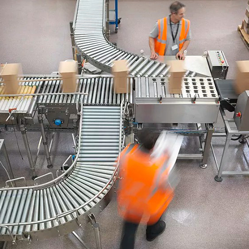
4. Integrating a Culture of Safety
In an environment with moving machinery and heavy loads, safety is not a feature—it is the foundation of the design.
Emergency Stop Systems: Large, easily accessible E-stop buttons must be placed at regular intervals along the conveyor. These are hard-wired into a safety relay circuit that cuts power to all motors immediately, overriding any software control.
Physical Safeguarding: Guards must be installed to prevent contact with pinch points, especially at transfer points, curves, and under the conveyor where return belts are located. These are often made of wire mesh or polycarbonate for visibility and durability.
Intelligent Sensing: Modern FPRs go beyond simple presence detection. Overload sensors can monitor motor current; a spike indicates a jam or obstruction, triggering an automatic shutdown. Zero-speed switches can detect if a roller has stopped turning despite the motor being powered, indicating a fault. Safety-rated light curtains can be installed at the loading/unloading interface to halt operation if a worker steps into a hazardous zone.

The Architect's Plan: A Step-by-Step Design Process
Transforming these considerations into a functional system requires a disciplined, iterative process.
Phase 1: Deep-Dive Requirement Analysis
This is the most critical phase. A design built on incomplete information is destined to fail. Engineers collaborate closely with clients to document:
Operational Purpose: Is it for truck loading, pallet handling, or small parcel sortation? Each has vastly different requirements.
Dimensional Constraints: Detailed facility drawings are analyzed, noting clearances, door widths, column locations, and ceiling heights.
Product Characteristics: A full spectrum of products must be defined—dimensions, weight, bottom surface type (cardboard, plastic, wood), and whether they are stable or prone to tipping.
Phase 2: Conceptual and Detailed Layout Design
Using CAD software, engineers create a 3D model of the entire system within the digital twin of the facility.
Path Optimization: The conveyor's path is plotted to minimize travel distance, avoid obstacles, and ensure efficient flow.
Integration Points: The model ensures seamless interfaces with other equipment: gravity conveyors, palletizers, sortation systems, and automated guided vehicles (AGVs).
Ergonomics and Maintenance Access: The layout must include safe spaces for operators and clear access panels for maintenance personnel to reach drives, sensors, and electrical panels.
Phase 3: Component Selection and Sourcing
With the layout finalized, every component is specified.
Rollers: Diameter, material (steel, polymer-coated), tube thickness, and bearing type are selected based on load and environmental conditions (e.g., washdown, cold storage).
Drive System: The choice between a centralized belt-drive system and a zoned MDR system is made, balancing initial cost against long-term flexibility and energy savings.
Control System Architecture: The brains of the operation are designed. This includes selecting the PLC (Programmable Logic Controller), specifying sensor types (photoelectric, ultrasonic, inductive), and designing the network (often Ethernet/IP) that will allow all zones to communicate.
Phase 4: Structural and Mechanical Design
This phase focuses on the physical realization of the design.
Frame Analysis: Using Finite Element Analysis (FEA) software, engineers simulate the stresses on the frame under maximum load and at maximum extension to validate the choice of materials and structural design.
Dynamic Mechanism Design: The engineering of movement—the hinging of segments, the telescoping mechanism, the scissor lift—is detailed, ensuring smooth operation and longevity.
Phase 5: Electrical System Integration
The control schematics are drafted, detailing every wire, sensor, motor, and I/O point on the PLC.
Power Distribution: The routing of power and communication cables through a flexible cable management system (e.g., energy chains) is designed to withstand constant bending without failure.
Safety Circuitry: The failsafe E-stop and safety sensor circuits are designed to be independent of the main control logic, ensuring safety even in the event of a PLC fault.
Phase 6: Rigorous Validation Through Testing
Before deployment, the system undergoes exhaustive testing.
Prototype Testing: A single section or a critical mechanism is built and tested to destruction to validate calculations.
Factory Acceptance Testing (FAT): The entire system is assembled at the manufacturer's facility and run for extended periods under simulated real-world conditions.
Site Acceptance Testing (SAT): Once installed on-site, the system is fine-tuned, and operators are trained, ensuring a smooth handover and immediate operational readiness.
Conclusion: Designing for an Adaptive Future
The flexible powered roller conveyor is more than just a tool; it is a testament to the evolution of industrial design towards modularity, intelligence, and human-centric operation. Its design process—a rigorous journey from operational analysis to final validation—ensures that it delivers not just movement, but optimized, safe, and adaptable flow. As logistics and manufacturing continue to demand greater agility, the principles underpinning the design of these sophisticated systems will become the standard, paving the way for even more intelligent and responsive material handling solutions. The future of conveyance is not fixed,it is flexible.